Whitechapel Computer Works
Whitechapel Computer Works (WCW) was an english computer manufacturer. Their first product was the NS32016 based workstation MG-1. Follow the link to Wikipedia to read more about WCW.
In October 2015 I got an information that an MG-1 without monitor was offered at ebay. The price of the offer was 1,950.00 £ . Although it is quite an interesting machine the price was in my opinion much too high.
In December 2021 I got an email from Phil. He worked for WCW from January 1985 until September 1986. He mentioned some technical details :
" Another project I did was a laser printer inteface, that DMA'd data out of main memory and sent it to a Laser Printer using a video-like interface
- since the image came directly out of main memory, it was fast for its day
- this functionality was enabled by the MG-1's use of an advanced AMD DMA controller that could chain together transfers and therefore gather Virtualised user space data into a continuous stream. I think it took a very talented s/w engineer to figure out how to do it though!
- we supported a Xerox print engine and a Canon print engine
Another neat trick was used to develop the CG-1 Colour Workstation
- since the key architectural decision was to support the video data out of main memory (Unified Memory, as it's now called), there wasn't judged to be enough bandwidth to support colour directly out of the main memory, so instead the monchome video bus was streamed into a dedicated video buffer on the Colour Card at around 10-15Hz, and this card could then support 60Hz refresh, with 8-bit colour with about 800 x 600 resolution. It definitely produced some interesting effects when updating the windows, but it was a practical solution to the market need to get a colour machine out the door!
- this wasn't my project, but it was great to see the CG-1 come together"
I asked Phil, why WCW did not use PALs for the MG-1. He wrote :
- "I did ask the same question myself at the time
- the answer I got was mainly the cost and speed - PALs at the time were considered expensive and not too fast (about 20ns propagation time) and also needed to be programmed in production"
Phil has saved some marketing brochures. Unfortunately they contain not many technical photos...
- MG-1 : the first computer model of Whitechapel
- CG-1 : the colour version of the MG-1
- MG-200 : the successor of the MG-1 is a 32-bit design based on a CPU module concept
- Whitechapel News : an overview for the customers of what is new at Whitechapel
Jim Austin's MG-1
During the visit of Jim Austin's computer museum in 2018 I saw the MG-1. Now I think the price was high, but maybe not too high ;-)
Unfortunately we were not able to power-on the MG-1. Something with the power supply seemed to be not working.
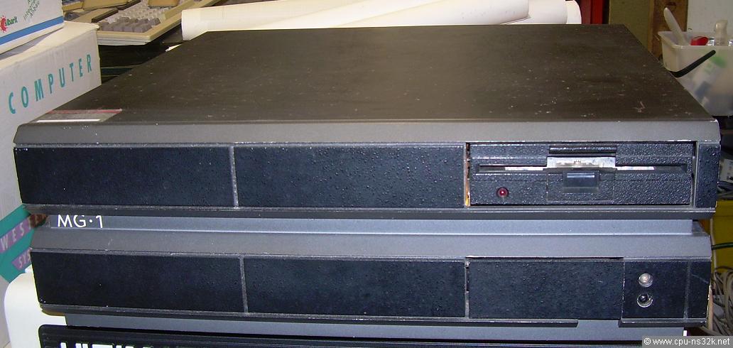
Fig. 1. The big, black box of the MG-1 looks impressive.
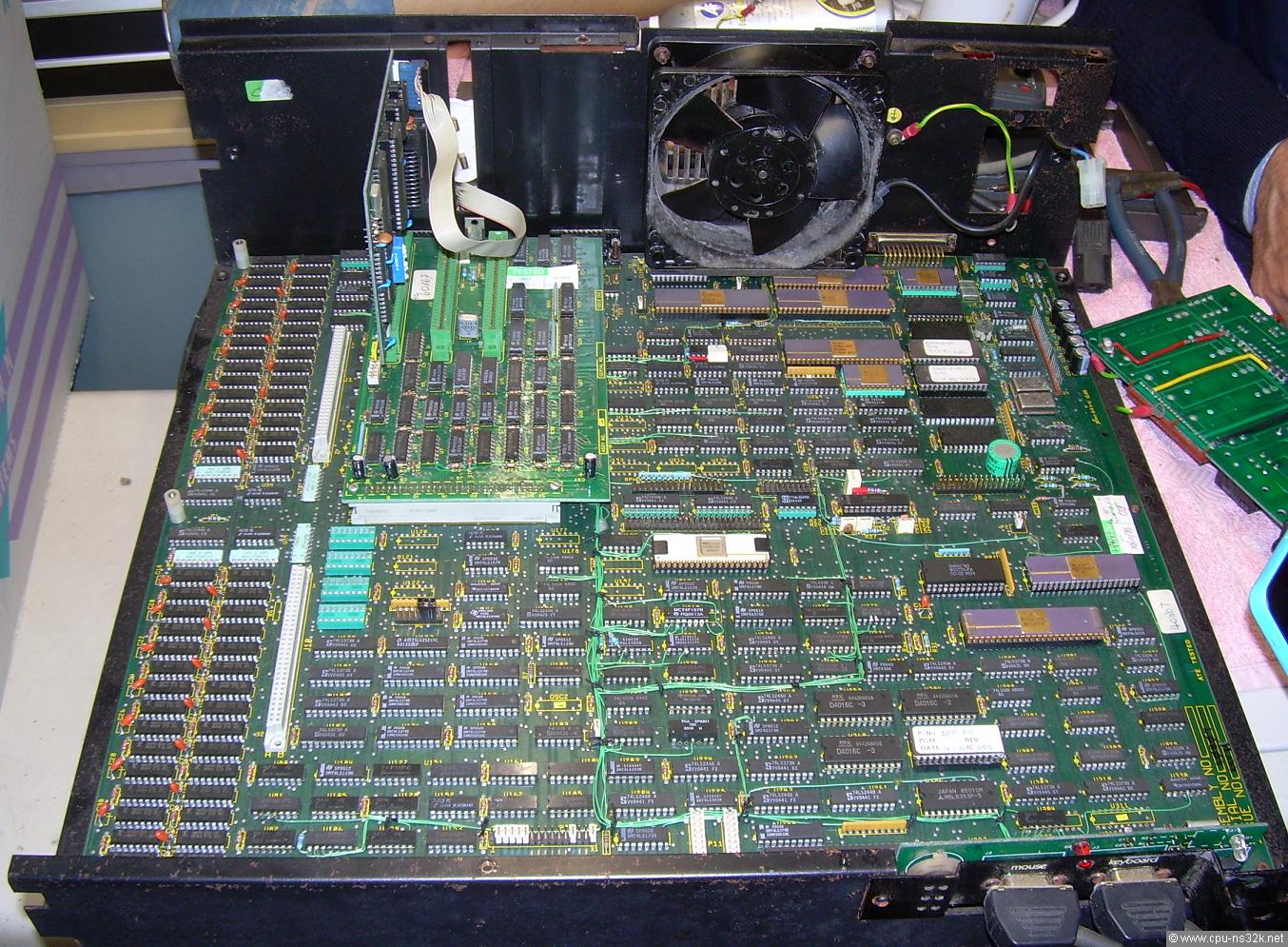
Fig. 2. The main board is huge. A lot of wires can be seen. Obviously there were some design fixes needed.
The memory size of the main board is 2 MBytes made of 256 kbit DRAM chips. They are placed at the left edge. Additional 6 MBytes can be added by up to three expansion cards.
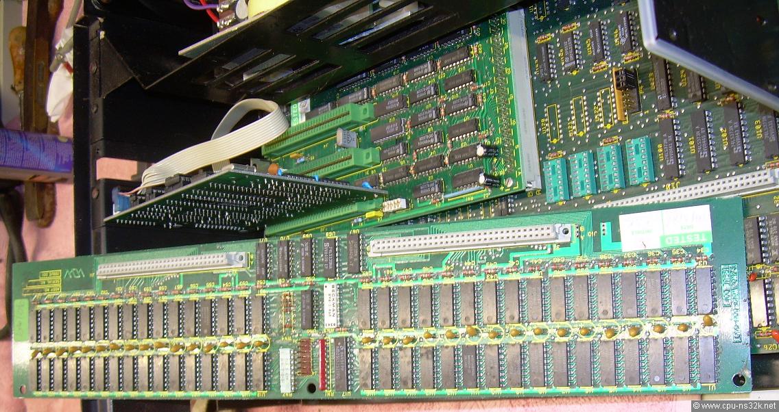
Fig. 3. The memory expansion card offers 2 MBytes of DRAM.
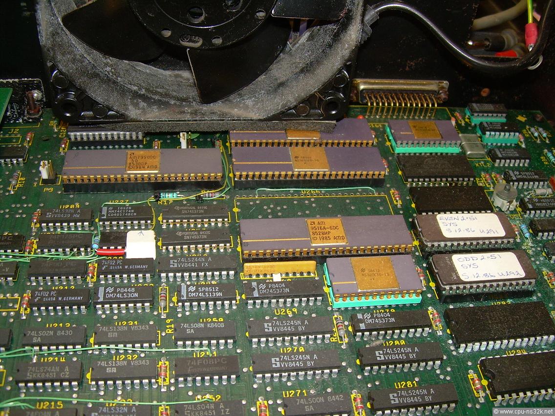
Fig. 4. A closer view of the CPU cluster shows more 48 pin devices not from National Semiconductor.
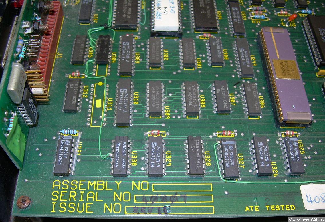
Fig. 5. Maybe the board was ATE tested but not the design. At the right another big chip from a different manufacturer. This time it is Motorola's MC68121.
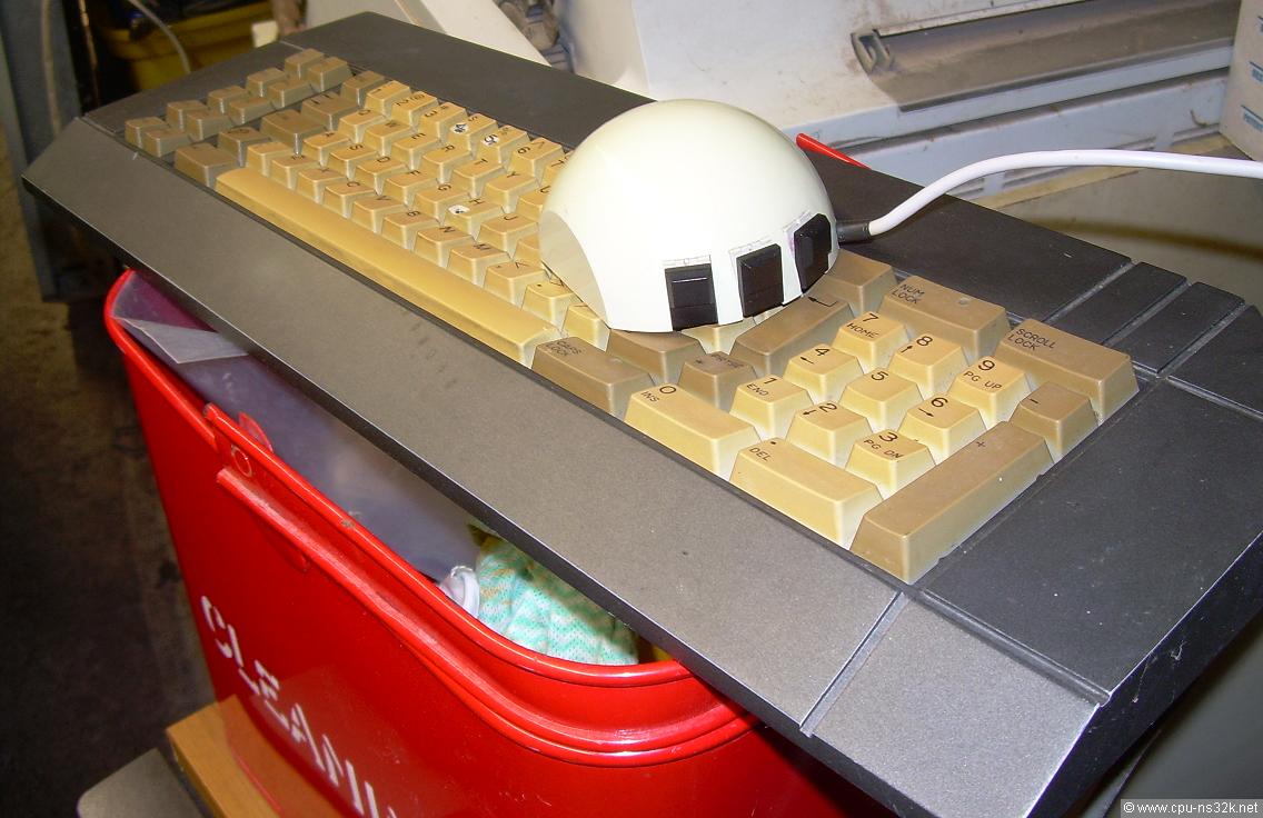
Fig. 6. A workstation must have a Mouse. Here it is together with the keyboard.
Tom's running MG-1
Seeing an old computer running is no big event. But it becomes one if the machine presents a feature which other computers do not have. This is the case with the Whitechapel MG-1.
In June 2020 I got a link to a video which shows the boot process of the MG-1. Wow, it runs on a GUI - see Figure 7! The MG-1 is an NS32016 based machine and I was not aware about its graphics capabilities. And even more astonishing is the fact that Tom's machine is running only at 8 MHz ! This catapults the MG-1 from being "nice" to being "exciting". Together with the fact that software is available it was only a short path to the decision that this computer must be included in TRIPUTER!
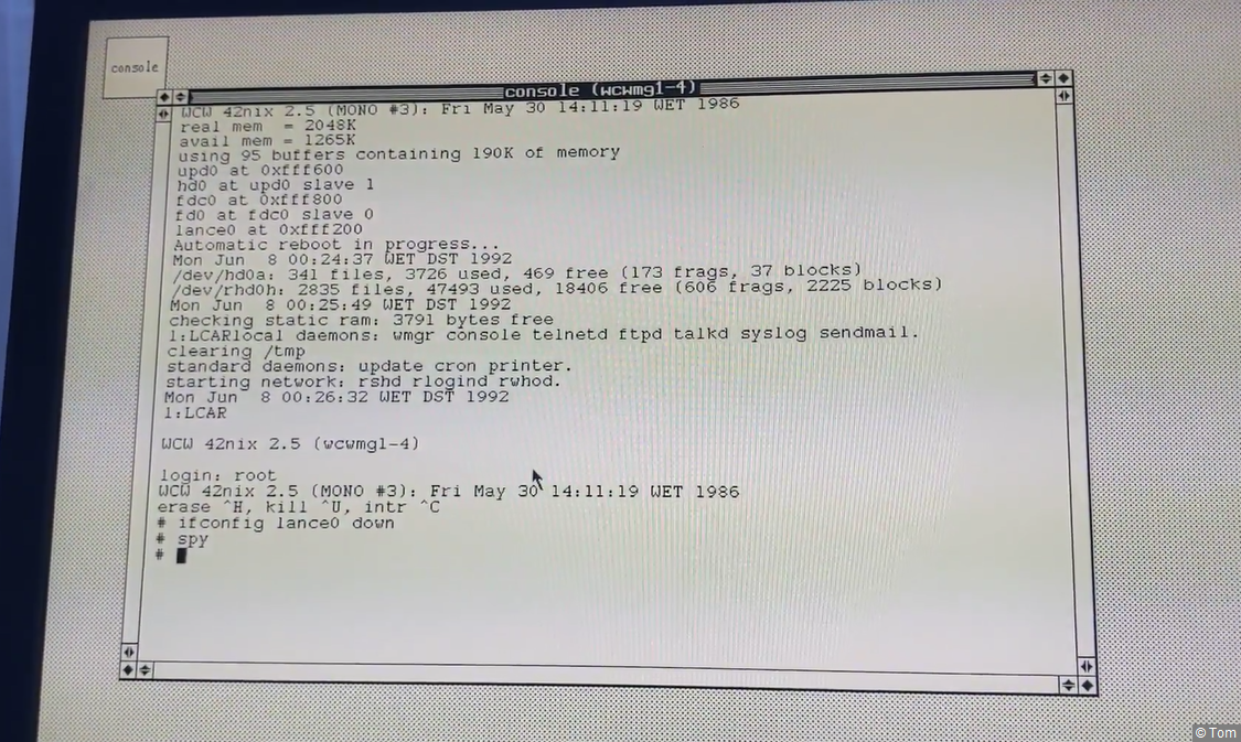
Fig. 7. A screenshot of the video showing the boot process of the MG-1 using a GUI !
The full video can be seen at Youtube. The screen shows 1024 black and white pixels by 800 lines. Screen refresh is 57 Hz. There is a 60 MHz oscillator on the board near the DRAMs. The frequency is no problem for TTL devices built in FAST technology. For example the 4-bit bidirectional shift register 74F194 can work up to 90 MHz. There is no need for ECL parts. I simply have forgotten how fast TTL could be 😊 .
Thank's to Tom who made this eyebrow rising video.
Tom's MG-1 in the Internet
Some days after I saw the video it became even more fascinating. Tom made an Ethernet connection from the MG-1 to a Raspberry Pi. From there he installed a VPN to Amazon, see Figure 8. He told me that no software must be written on the MG-1. Everything needed was already available.
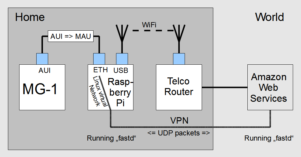
Fig. 8. The system architecture to link the MG-1 to the Internet.
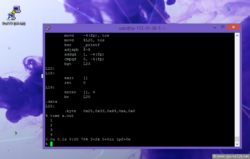
Fig. 9. I uses PuTTY to access Tom's MG-1. The assembler code is generated by the compiler cc using the -S option.
Tom: thank you very much for this experience!
And now comes the latest news : Tom uses his MG-1 as a web-server! Go to the cool address http://mg-1.uk/ . Tom said about the old computer : "it operates on a "best effort" basis and shouldn't be relied on. You never know; maybe tomorrow it could go down forever."
System description and more
The following items give a detailed insight of the MG-1 :
- a description of the system : binder 1 *) (Phil has written this document on a VAX 11/750 using emacs and troff for text formatting)
- a collection of hand made schematics : binder 2 *)
- all original schematics (from a copy of a copy) : circuit diagrams *)
- a high resolution photo of the main board : image
- the system ROM at archive.org
- the IO processor ROM also at archive.org
- a description of the GUI at chilton-computing.org
- NEW: thanks to Hector the user manual of the MG-1 is available : MG-1 Owner Operator Guide

*) These scans are from the collection of Tony Duell, who also made the hand-drawn schematics after reverse-engineering the components they describe.
Phil has also done the schematic for the prototype of the first CPU board for the MG-200 : NS32332 circuit diagram
The The John Gabriel Byrne Computer Science Collection at the Trinity College Dublin (TCD) in Ireland has an MG-1 in its collection. A number of photos showing the outside and the monitor can be found in the document TCD-SCSS-T.20121208.058.pdf.
There is a plan under way to rebuild the MG-1 with most of the original parts. The job becomes not easy, but feasible with all the available information. Watch this chapter to see any news!
Vince's MG-1
Vince bought the MG-1 on ebay. The computer arrived at him in a bad condition. The backup batteries for the SRAM had leaked. They are located on a small board that delivers all the power to the computer. This board was unfortunately missing. Vince cleaned the dirty area as best he could.
In September 2025 I visited Vince. We wanted to see how far we can get with bringing up again this machine.
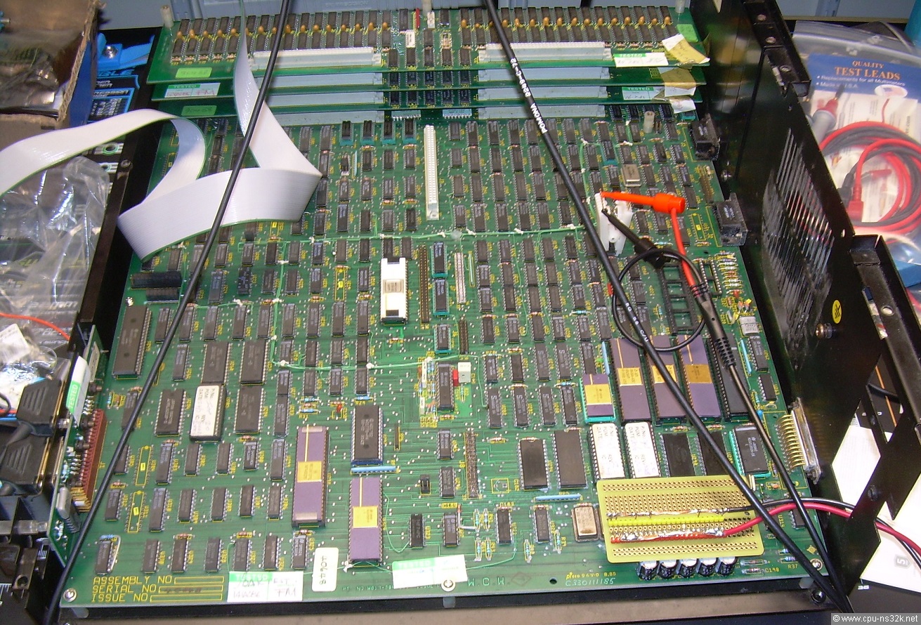
Fig. 10. 5V is applied to the MG-1 - nothing went into smoke. Of course we measured first whether there is a short between 5V and ground.
When we first applied power to the MG-1 the amount of current drawn was 8.5A . This is a good value for a computer being equipped with the maximum amount of memory of 8 MByte. The video signals hsync and vsync were alive. They are generated by hardware and therefore it is no big wonder but it was a good sign.
The NS32016 CPU seems to have problems. There was no active signal at the /CE pin of the EPROMs. Next we applied a square wave signal to the reset pin to see what happens after reset. After we took the CPU out of the socket and into it again we saw some activity at the /CE pin. At the end of the day it became clear that we have to fully understand what the CPU is normally doing and expecting from the system. For this purpose we have to look deep into the monitor program - this will be an ambitious task. But the first results were not so bad. Vince and I are optimistic that we can bring up his MG-1 again.
Second Workshop on Vince's MG-1
From July 28 to first of August 2026 I visited Vince. We worked hard for three days to bring-up his MG-1.
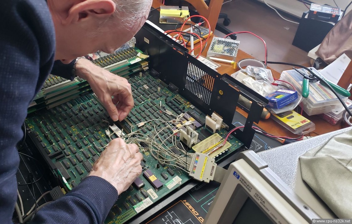
Fig. 11. Me at work inside the MG-1 - I felt like a doctor examining a patient.
We first changed the program EPROMs. It was already clear before my journey that the content was not correct. We used the program of Tom's MG-1. But this did not change the behavior of Vince's MG-1. For two days we tried to analyze with the help of an Hewlett Packard logic analyzer 1670A what goes wrong. But with no result.
On the last day we decided to write a radical simple test program. Vince had the idea to use an opcode with the interlock signal of the CPU NS32016 to become active. This can be done with the opcode SBITI = "Set Bit Interlocked". The next opcode is a branch back. First we used EPROMs but later Vince found some 64 kBit EEPROMs in his big collection of chips. They were not in use since he bought them many years ago. EEPROMs are much better for writing multiple test programs because they do not require UV light for erasing.
To be honest, I was not expecting a positive result. But the unthinkable happened - the program worked as intended. Okay, it was not stable. Switching MG-1 on and off again showed sometimes wired results. But we got a stable image on the oscilloscop which is shown in Figure 12.
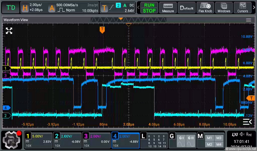
Fig. 12. The oscilloscop screen shot shows the stable operation of MG-1. What a proud moment!
The signals are:
- Signal 1 : the address strobe signal at an SN74373 register
- Signal 2 : the interlock signal of the CPU NS32016 (in MG-1 not used)
- Signal 3 : the CS of the program EEPROM
- Signal 4 : the CS1 signal of the SRAM type 5516 where the bit is set (CS2 is used for power down)
The opcode SBITI makes two accesses to the SRAM: the first is a read cycle for the byte with the desired bit, then follows an internal operation setting the bit in this byte and finally a write cycle to the previous address. This behavior can be seen clearly on the screen shot.
A read access of either the EEPROM or the SRAM takes 8 clock cylces : T1-T4 + Tmmu + 3 wait states. The speed of the SRAMs and EPROMs would allow to reduce the number of wait states to two. This would improve the performance by 12.5%. But it is at the moment unclear how often these chips are accessed in normal operation.
After some more power-on and power-offs it became clear that the clock circuitry has a problem. We could improve the situation by connecting an oscillator to the TCU NS32201.
Our next test program did a blinking of one LED. The system has only three LEDs, one for power which is always on. One is on the floppy drive which is currently not available and one is used for the error status. This one was blinking with the right speed - the next success!
Due to the positive results we wrote a more complex program - see the next Figure.
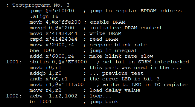
Fig. 13. The last test program was much more complex - and it worked! At least most of the time...
And the program did a slow blinking. This means that the DRAM accesses work correct! Champagne...
Now we have a good feeling about the status of Vince's MG-1. Many things are working and it can only be a matter of time to find the problems which prevents the boot program from starting the machine.
We stopped writing of another test program because the sockets of the EPROM/EEPROMs were much stressed by taking the chips in and out. Vince will install ZIF-sockets later and continue with new test programs.
After the workshop Vince took the pcb of MG-1 out of its case. For the first time a view of the backside was possible. Vince wanted to replace the power connector which was damaged due to the leakage of the backup batteries.
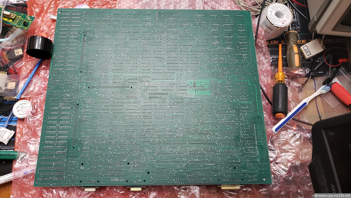
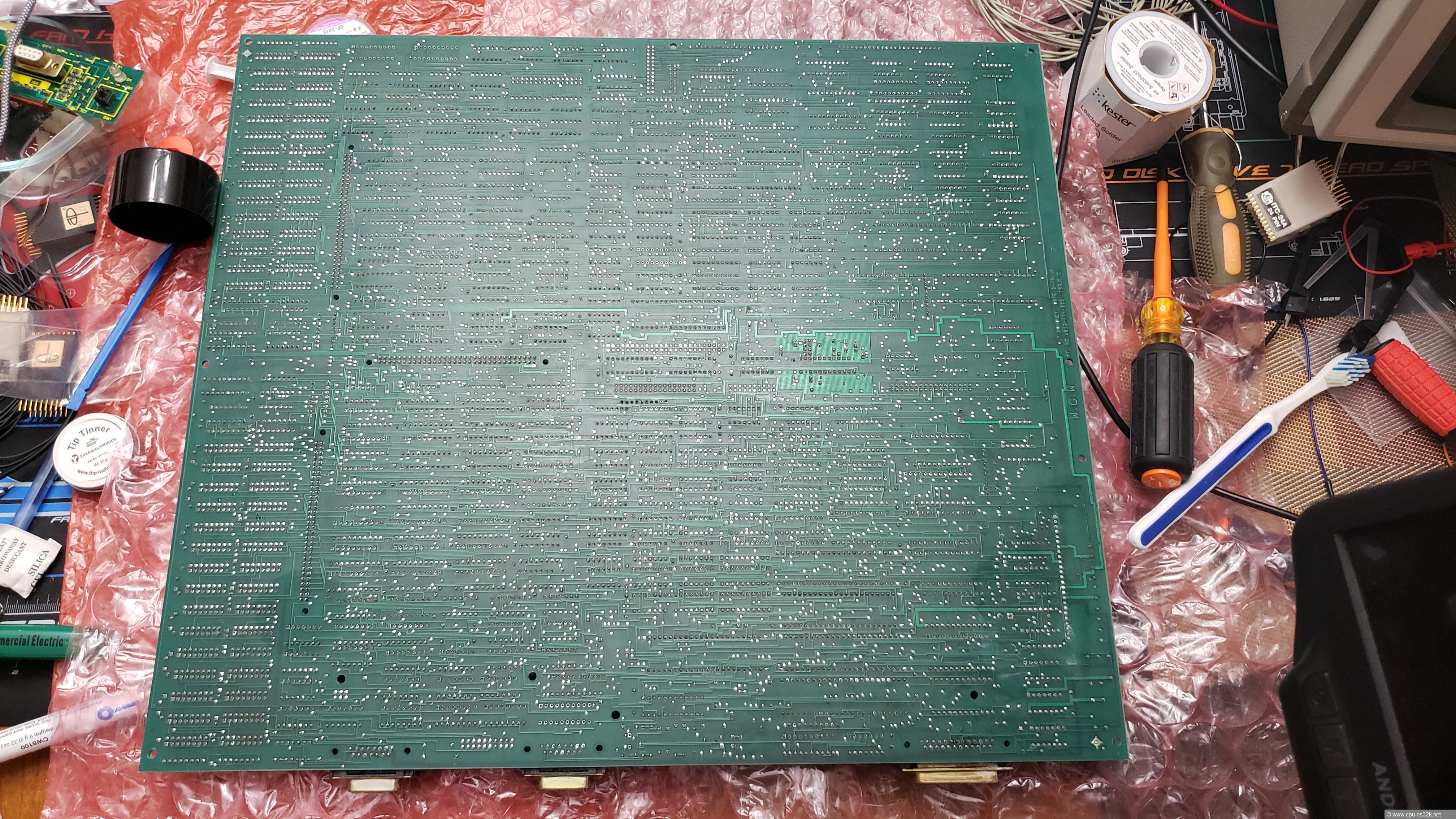
Fig. 14. The backside of the pcb of MG-1 looks fine and shows no rework. I have no idea what the toothbrush was used for...
The image of Figure 14 is available in higher resolution here .
This chapter was last modified on 15 August 2026. Next chapter: M32632/Overview